Speed and Reference Sensors — Checking, Replacement, and Adjustment
Information, resistance specs, operational checks, replacement procedure, and clearance adjustment for the crankshaft speed sensor and reference sensor on the 944 engine management system.
Denne prosedyren er ikke oversatt ennå og vises på engelsk.
Introduction
The 944 engine management system uses two crankshaft sensors:
- Reference Sensor: Determines the position of piston number 1 (front of engine) relative to top dead center (TDC) on the compression stroke.
- Speed Sensor: Counts the teeth on the flywheel and sends RPM information to the DME computer as a series of pulses.
The DME uses both signals together to determine engine position at any point in its cycle, enabling correct fuel injector timing and ignition firing. The speed sensor signal also acts as a safety feature — after initial cranking is complete, the DME shuts down the fuel pump if engine speed falls below 300 RPM.
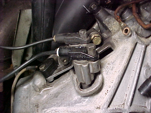
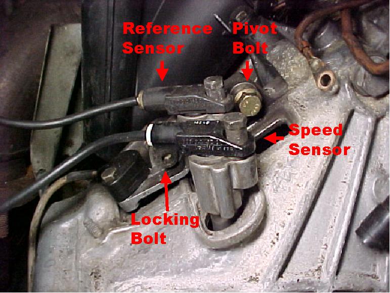
Both sensors are located on top of the clutch housing at the back of the engine, visible from the driver's side near the firewall.
Tools
- 10 mm socket or 5 mm Allen head socket (depending on sensor retaining bolt type)
- 6 mm Allen head socket
- 0.8 mm thick washer (for sensor clearance adjustment)
- Multi-meter
- Oscilloscope (optional, for operational signal check)
Checking Sensor Operation
Resistance Checks
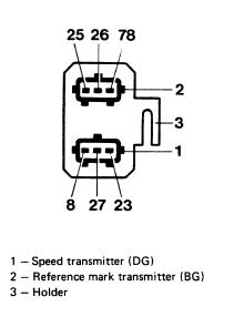
- Disconnect the sensor plug connector at the back of the engine compartment.
- Check sensor resistances with a multi-meter:
Speed Sensor
| Terminals | Specification |
|---|---|
| 8 – 27 | 600–1,600 ohms |
| 8 – 23 | > 1 M-ohm |
Reference Sensor
| Terminals | Specification |
|---|---|
| 25 – 26 | 600–1,600 ohms |
| 25 – 78 | > 1 M-ohm |
Operational Signal Check
An oscilloscope test confirms whether the sensors are providing usable signals to the DME. A multi-meter can detect whether a signal exists but cannot confirm its magnitude, so it will not reveal whether the signal is strong enough for the DME to read.
- Remove the fuel pump fuse.
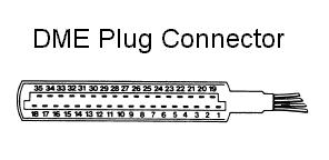
- Disconnect the DME computer plug.
- To check the speed sensor: connect an oscilloscope from terminals 8–27 on the DME plug. Crank the vehicle and look for a sawtooth wave with a peak-to-peak voltage above 2.5 V.
- To check the reference sensor: connect an oscilloscope from terminals 25–26 on the DME plug. Crank the vehicle and look for periodic pulses with a peak-to-peak voltage above 2.0 V.
- If either voltage is below specification, check sensor clearance per the "Adjusting Sensor Clearance" section below.
Note: A quick non-oscilloscope check: crank the vehicle and watch the tachometer. If the tach needle jumps during cranking, the speed and reference sensors are likely functioning. If it does not move, the sensors or the DME may be at fault.
Sensor Removal
- Disconnect the battery negative lead.
- Disconnect the speed and/or reference sensor connectors at the back of the intake manifold.
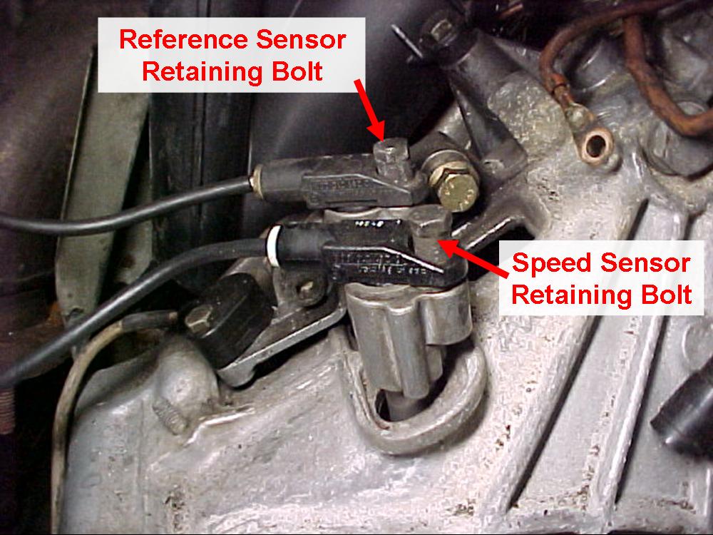
- Remove the sensor retaining bolt (5 mm Allen head socket or 10 mm socket, depending on bolt type).
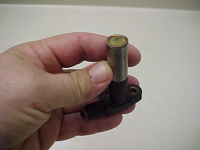
- Twist the sensor side to side while pulling upward to free it from the mounting bracket.
Sensor Installation
-
If both sensors are being replaced, verify correct installation using the labels on the wiring harness and the mounting bracket:
Wiring harness labels:
- DG = Speed Sensor
- BG = Reference Sensor
Mounting bracket labels:
- D = Speed Sensor
- B = Reference Sensor
If the mounting bracket labels are unreadable, the sensor closest to the firewall is the speed sensor.
-
If the sensor mounting bracket has been moved or alignment is uncertain, perform the "Adjusting Sensor Clearance" procedure below.
-
Install the sensors and retaining bolts. Torque retaining bolts to 8 Nm (6 ft-lbs).
-
Reconnect the battery negative lead.
Adjusting Sensor Clearance
Sensor clearance adjustment is only required if the sensor mounting bracket has been removed or the mounting bracket locking bolt has been inadvertently loosened. Replacement sensors do not normally require adjustment.
- Remove the speed sensor.
- Loosen the mounting bracket locking bolt (6 mm Allen head) and pivot bolt; re-tighten both finger-tight.
- Glue a 0.8 mm thick washer to the bottom of the speed sensor.
- Install the sensor with the washer attached and tighten.
- Move the bracket down until it stops against the ring gear on the flywheel.
- Tighten the mounting bracket locking bolt and pivot bolt.
- Remove the sensor with washer.
- If the sensor is to be reused, pry the washer off.
- Install the sensor and torque the retaining bolt to 8 Nm (6 ft-lbs).
- Reconnect the battery negative lead.