Cooling Fan Troubleshooting — Early Cars with A/C
Early cars with air conditioning use two cooling fans and an A/C relay. Operation, a symptom-to-cause guide, and relay / A/C-relay / thermofan-switch test procedures.
COOLING FAN TROUBLESHOOTING
PORSCHE 944 · EARLY CARS · A/C
Pick the symptom you have to start the diagnosis.
Cooling Fan Operation
On early cars equipped with air conditioning, there are two electric cooling fans. The driver's side fan is supplied via a parallel circuit: one leg contains a resistor (slow speed), the other leg contains a contact in the cooling fan relay (fast speed). The passenger's side fan is supplied via a contact in the cooling fan relay.
When coolant temperature reaches approximately 92 °C198 °F, the thermofan switch closes and causes the driver's side fan to run in slow speed (the slow-speed resistor remains in circuit). The fan will run as long as temperature remains above the setpoint, regardless of whether the ignition is on — this is a common problem source.
When the ignition is on and the A/C is turned on, the A/C relay picks up, which energises the cooling fan relay. This closes two contacts: one starts the passenger's side fan (always fast speed); the other shorts out the slow-speed resistor for the driver's side fan, running it in fast speed. The driver's side fan also runs regardless of coolant temperature whenever the A/C is on.
When the ignition is on and a high-temperature condition is sensed by the thermofan switch, the relay is energised and both fans run in fast speed.
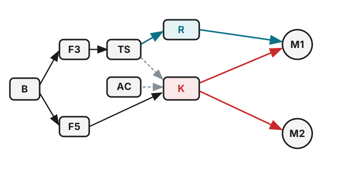
Early circuit with A/C: (B) battery feed · (F3/F5) fuses · (TS) thermofan switch · (AC) A/C relay · (K) cooling-fan relay · (R) slow-speed resistor (driver's side) · (M1) driver's-side fan · (M2) passenger's-side fan.
Cooling Fan Troubleshooting
Identify the symptom you are seeing, then jump to the likely cause below.
Note: This guide assumes a single failure is causing the fault. Multiple simultaneous failures can occur, but covering every combination is impractical — diagnose one cause at a time.
Blown fuse
One or both fans will not run. Auxiliary Fuse Panel: Fuse 3 — Driver's Side Cooling Fan; Fuse 5 — Passenger's Side Cooling Fan.
Bad fan motor
One or both fans will not run. Disconnect the connector at the fan and take resistance readings. Infinite resistance or a ground indicates a bad motor. It is highly unlikely for both motors to fail simultaneously.
Bad slow-speed resistor
A fan runs but not in slow speed (it still runs in fast speed). Locate the slow-speed fan resistors on the firewall behind the tachometer; resistance should be less than 1 ohm. Infinite resistance = open; higher than 1 ohm = partial failure. It is highly unlikely for both resistors to fail simultaneously.
Bad cooling fan relay
One or both fans will not run. With a bad relay, the driver's side fan should still run in slow speed on high coolant temperature. See Testing the Cooling Fan Relay.
Bad thermofan switch
The driver's side fan runs continuously with the ignition OFF, or both fans run continuously with the ignition ON. Disconnect the thermofan switch connector; if the fan(s) stop, the switch is bad. (With the ignition off, both the switch and the relay would have to fail simultaneously to cause this.) See Testing the Thermofan Switch.
Bad A/C relay
Both fans run continuously with the ignition ON — remove the A/C relay; if the fans stop, it is most likely bad. Otherwise a bad A/C relay only prevents the fans from running when the ignition and A/C are on; both fans should still run in fast speed on high coolant temperature. See Testing the A/C Relay.
Testing the Cooling Fan Relay
Tools needed:
- 12 VDC power supply and leads
- Multimeter with alligator clip leads
Procedure:
- Remove the Cooling Fan Relay.
- Take resistance readings with the relay de-energised:
- Terminals "A" to "B" — should be infinite (open circuit)
- Terminals "30" to "87" — should be infinite (open circuit)
- Connect a 12 VDC power supply across terminals "85" and "86". You should hear the relay click.
- With power supply connected, take resistance readings:
- Terminals "A" to "B" — should be zero (short circuit)
- Terminals "30" to "87" — should be zero (short circuit)
- If any reading above is bad, the relay is bad and should be replaced.
Testing the A/C Relay
Tools needed:
- 12 VDC power supply and leads
- Multimeter with alligator clip leads
Procedure:
- Remove the Air Conditioning Relay.
- Take resistance readings with the relay de-energised:
- Terminals "A" to "B" — should be infinite (open circuit)
- Terminals "30" to "87" — should be infinite (open circuit)
- Connect a 12 VDC power supply across terminals "85" (positive) and "86" (negative). You must connect positive to terminal 85 — there is a diode in the circuit that will prevent the relay from working if you reverse polarity.
- With power supply connected, take resistance readings:
- Terminals "A" to "B" — should be zero (short circuit)
- Terminals "30" to "87" — should be zero (short circuit)
- If any reading above is bad, the relay is bad and should be replaced.
General Circuit Testing
Tools needed:
- Multimeter
- Electrical jumpers
Test 1 — Slow Speed (Driver's Side Fan)
- Disconnect the thermofan switch connector (below the upper radiator hose connection at the radiator).
- Jumper the contacts in the electrical connector.
- The driver's side fan should run in slow speed.
A successful test confirms that power supply to the driver's side fan via the slow-speed resistor is intact.
Test 2 — Fast Speed (Both Fans)
- With the thermofan switch connector still jumpered, turn the ignition on.
- Both cooling fans should run in fast speed.
A successful test confirms that power supply to both fans is good and that both fans and the cooling fan relay are working properly.
Test 3 — A/C Mode Fast Speed (Both Fans)
- Remove the jumper from the thermofan switch connector.
- With the ignition on, turn on the A/C switch.
- Both cooling fans should run in fast speed.
A successful test confirms that the power supply, both fans, the A/C relay, and the cooling fan relay are all working properly.
Testing the Thermofan Switch
Tools needed:
- Thermometer (rated to at least 93 °C199 °F)
- Multimeter
Procedure:
- Connect a multimeter across the contacts on the thermofan switch. At room temperature, contacts should be open (infinite resistance).
- Suspend the thermofan switch in a pan of water. Insert the thermometer to monitor temperature.
- Heat the water. When temperature reaches 92 °C198 °F, the contact should close (zero resistance on multimeter).
Repairing Fan Relays
If the cooling fan relay is confirmed bad, inspect it before purchasing a replacement. Like many electronic components on the 944, the fan relay is susceptible to cracked solder joints. Open the relay and inspect the board with a magnifying glass — cracks will be approximately the width of a human hair. If any joint looks suspect, re-solder it.
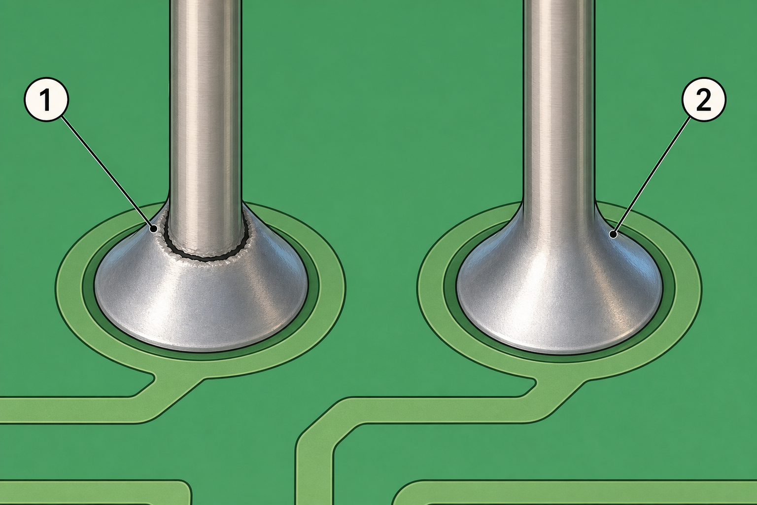
Close-up of the failure mode: (1) a hairline solder crack — a ring fracture around the pin; (2) a good joint for contrast.