DME Self-Diagnosis and Troubleshooting (8-valve)
A structured test-point diagnosis of the 8-valve DME (Digital Motor Electronics) fuel-injection and ignition system: equipment, safety rules, and fifteen sequenced test points covering no-start, hard-start, misfire, and poor-running faults — each with the factory pass/fail values.
DME DIAGNOSIS
PORSCHE 944 · 8-VALVE
Pick the symptom you have to start the diagnosis.
Auxiliary fuse box — early cars
| № | Rating | Protected circuit |
|---|---|---|
| 2 | 16 A | Fuel pump |
The 8-valve cars use a Bosch DME (Digital Motor Electronics) unit that controls both fuel injection and ignition from one control unit. When an engine will not start, is hard to start, misfires, or runs poorly, the factory diagnosis is a fixed sequence of fifteen test points. Each one isolates a part of the system with a specific measurement; this guide reproduces that sequence with the factory pass/fail values.
Note: Work through the test points in order, especially when the complaint is an engine that will not start or is hard to start. Each test assumes a single fault is causing the problem — diagnose one cause at a time. Use the symptom guide above to jump to the most likely starting test point.
Test equipment
- An engine oscilloscope (the factory procedure was written around the SUN 1010 / SUN 1080 and Bosch MOT 002.01 shop testers — any equivalent automotive oscilloscope works; the connection points and expected signals below are what matter).
- A multimeter with an internal resistance of at least 20 kΩ/V.
- An injector adapter lead (Bosch "L-Jetronic" No. 1684 463 093) for the injection-timing trace.
- A fuel-pressure gauge (P 378 or VW 1318).
- Two shop-made test leads about 50 cm (20 in.) long — highly flexible wire, an insulated lead clip, and a flat male plug 2.8 (N 17.457.2) — for back-probing the multi-pin plug on the DME control unit and connectors with the same female plug version (timer contacts).
Safety precautions
Observe these measures to avoid destroying the DME system. The control unit is easily damaged by mishandled battery and welding currents.
- Never start the engine without a connected battery.
- Reversing the battery connections can destroy the control unit.
- Never start the engine with a quick charger connected. To assist starting, use a separate 12 V battery only.
- Disconnect the battery before quick-charging it.
- Never disconnect the battery while the engine is running.
- Connect or disconnect the multi-pin plug on the control unit only with the ignition off.
- The ground wire between engine and body must be connected before starting the engine — for example after reinstalling the engine — otherwise the DME control unit will be destroyed.
- Disconnect the multi-pin plug on the DME control unit before any electric welding.
- Pull off the fuel-pump relay before a compression test.
Note: The same dangers that apply to electronic ignition systems apply here — observe the ignition-system safety rules as well.
To remove the DME control-unit plug, push the catch toward the right side and at the same time pull the plug off forward.
Diagnostic test points
Test point 1 — Ground and plug connections
Most DME faults trace back to a bad ground or a loose connector, so this is always the first check.
- Check both ground connections next to the pulse transmitters for cleanliness and firm contact.
- Check the ground connection between engine and body.
- Check each of the following plug connections for tight fit, bent plug sleeves, and corrosion:
- DME control unit
- speed and reference-mark transmitters
- air-flow sensor
- throttle switch
- temperature sensor II (engine temperature)
- fuel injectors
- the plug above the brake booster
- the fuel-pump relay socket
Note: Frequent removal and installation of the fuel-pump relay can loosen and push back the catch for the flat female plugs — check it.
Test point 2 — Power supply (control unit and fuel pump)
DME control unit. Turn off the ignition and pull off the multi-pin plug on the control unit. Turn the ignition on and measure the voltage between terminal 35 and terminal 5, and between terminal 18 and terminal 5.
- Specification: battery voltage.
Always use the extra test wires to connect the tester. If the voltage deviates from battery voltage, check the fuel-pump relay, the 9-pin plug connection above the brake booster (terminals 2 and 3), and the corresponding wires. Turn off the ignition and reconnect the multi-pin plug afterward.
Fuel pump. If the pump does not run while cranking:
- Check fuse 2 (16 A) in the auxiliary fuse box.
- Check the fuel-pump relay.
- Supply battery voltage to terminal 4 of the 9-pin plug above the brake booster, or bridge terminals 30 and 87b on the fuel-pump relay socket. The fuel pump should then run.
Test point 3 — Speed transmitter
An oscilloscope is used to check the speed and reference-mark transmitters.
- Turn off the ignition and pull off the multi-pin plug on the DME control unit.
- Connect the oscilloscope across terminal 8 (signal) and terminal 5 / 27 (return) of the DME plug and adjust it.
- Start the engine.
A sine oscillation must appear, with an amplitude of more than 2.5 V peak-to-peak.
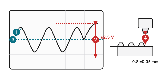
Transmitter signal: (1) the sine wave must begin on a positive-going slope · (2) peak-to-peak amplitude must exceed the minimum (2.5 V for the speed transmitter; 2 V for the reference-mark transmitter at a starter speed of at least 200 rpm) · (3) the zero/trigger line · (4) the air gap between transmitter and starter ring gear: 0.8 ±0.05 mm.
If the signal is less than 2.5 V, check the air gap between the starter ring gear and the transmitter.
- Specification: 0.8 ±0.05 mm.
If no signal appears despite a correct connection and a correctly adjusted tester, measure the speed transmitter's power flow and insulation:
- Coil resistance, terminal 8 against terminal 27: 0.6 to 1.6 kΩ.
- Insulation resistance, terminal 8 against terminal 5: more than 1 MΩ.
Replace the speed transmitter if necessary.
Note: The original procedure listed detailed dial settings for period shop testers (SUN 1010 / SUN 1080, Bosch MOT 002.01). The electrical connections and signal values above are what carry over to any oscilloscope.
Test point 4 — Reference-mark transmitter
Adjust the oscilloscope as in test point 3. Connect it across terminal 25 and terminal 26 of the DME plug and start the engine.
A single sine oscillation must appear. It must begin with a positive slope and show more than 2 V on the screen at a starter speed of at least 200 rpm (the amplitude depends on starter speed).
If the signal is less than 2 V, check the air gap between the transmitter and the reference mark.
- Specification: 0.8 ±0.05 mm.
If there is no signal, proceed as for the speed transmitter in test point 3 — the same coil- and insulation-resistance specifications apply.
Test point 5 — Ignition system
Set the oscilloscope to the secondary pattern across terminals 1 and 15, with the trigger clip on cylinder 1.
Note: A defect shown on all cylinders lies in the primary or secondary circuit between the ignition coil and the distributor rotor. A defect on one cylinder lies after the distributor rotor.
- Check the distributor cap for damage, burnt spots, and dirt. The retaining hooks must engage firmly on installation.
- Check the distributor rotor — shielded resistance 1 kΩ — for tight fit, damage, and dirt.
- Check the spark-plug caps and leads for damage or traces of burning — shielded resistance 3 kΩ.
- Check the ignition coil:
- primary resistance, terminal 1 against 15: 0.4 to 0.6 Ω
- secondary resistance, terminal 1 against 4: 5 to 7.2 kΩ
- check visually for damage or burnt spots.
- Check ignition timing at idle with the engine at operating temperature: 5 to 15° before TDC at 800 ±50 rpm.
Caution: Do not check the ignition system through the spark gap by pulling off the spark-plug caps — this can destroy the ignition coil and control unit.
Test point 6 — Air-flow sensor
- Push back the protective sleeve of the air-flow sensor connector (leave the connector attached) and connect a voltmeter to terminals 9 and 6 on the rear of the connector. Specification: more than 8 V.
- Remove the air cleaner and connect a voltmeter between terminal 7 and ground. Specification: approx. 150 to 250 mV.
- Push the sensor plate to the full-throttle position with a smooth, not-too-hard item inserted through the filter intake opening. Voltage rises above 8 V with the plate fully open (the test range switches over). The sensor plate must not stick, and must return to the off position on its own when released.
- Check temperature sensor I (intake-air temperature): turn off the ignition, pull off the air-flow-sensor plug, and connect an ohmmeter between terminals 6 and 22 (both outer flat male plugs). Specification at 15 °C59 °F to 30 °C86 °F: 1.45 to 3.3 kΩ.
Note: An interruption on the temperature sensor causes a richer mixture; a short causes a leaner mixture.
Test point 7 — Fuel pressure
- Open the flap on the distribution tube and unscrew the capped nut on the test connection.
- Connect the fuel-pressure tester (P 378) to the distribution tube.
- Start the engine and measure fuel pressure at idle. Specification: approx. 2.0 bar29 psi.
- Pull the vacuum hose off the pressure regulator — fuel pressure should rise. Specification: 2.3 bar33 psi to 2.7 bar39 psi.
- If the pressure deviates from these values, slowly pinch the return line shut with a clamp.
If pressure rises above 4 bar58 psi, replace the pressure regulator. If pressure stays below 4 bar58 psi, check the fuel filter or replace the fuel pump.
Tightening torque for the capped nut: 22 N·m16 ft·lb.
Caution: Take care that the sealing ball does not fall out when removing the capped nut. Catch escaping fuel — an electric spark could cause a fire.
Test point 8 — Fuel injectors and injection timing
Checking the injectors. If the engine runs, disconnect the injector plugs one at a time — the engine speed should drop each time if the injector is good. If the engine cannot be run, measure the voltage on one injector plug connection against ground: one of the two terminals must have battery voltage (if not, perform test point 2). Then measure the coil resistance on the flat male plugs of the injector. Specification: 2 to 3 Ω.
If the engine will not run, supply battery voltage to terminal 4 of the 9-pin plug, or bridge terminals 30 and 87b on the fuel-pump relay socket, so the pump runs (fuel pressure 2.3 bar33 psi to 2.7 bar39 psi).
Checking injection timing. Adjust the oscilloscope as in test point 3 and connect the adapter lead (Bosch "L-Jetronic" No. 1684 463 093) between one fuel injector and its matching plug. Start the engine; with correct injection timing, the scope shows the characteristic patterns at starter speed, idle, acceleration, and deceleration (where ti = injection time). If the injection signal does not switch off while decelerating, see test point 10.
Test point 9 — Temperature sensor II (engine temperature)
- Check the plug for tight fit and the receptacles for cleanliness and contact.
- Connect an ohmmeter between terminal 13 on the disconnected DME plug and ground:
- at 15 °C59 °F to 30 °C86 °F: 1.45 to 3.3 kΩ
- at 80 °C176 °F: 280 to 360 Ω
If the measured values deviate, repeat the test at the temperature sensor itself and replace it if necessary.
Note: A break on the temperature sensor causes a richer mixture; a short causes a leaner mixture.
Test point 10 — Throttle switch
- Connect an ohmmeter between terminal 2 on the DME plug and ground:
- throttle closed: zero ohm
- throttle open: infinite ohms
- the switch-over must take place even when the throttle is only slightly open (approx. 1°).
- Connect an ohmmeter between terminal 3 on the DME plug and ground:
- throttle closed: infinite ohms
- throttle wide open: zero ohm
- switching must take place immediately before full throttle.
If the switching points are wrong, repeat the test directly on the throttle switch by connecting the ohmmeter to terminal 18 (ground; the center flat plug on the throttle switch) and terminal 2 or terminal 3.
Adjusting the throttle switch. Remove the throttle housing, unscrew the switch mounting screws, hold the throttle in the closed position and turn the switch until the inner stop is felt (the throttle must not move), then tighten the screws — the throttle must rest firmly on the stop screw.
Checking coasting shut-off (stop of injection signal). Pull off the plug on the throttle switch and connect terminal 2 (idle contact) and terminal 18 to simulate a closed throttle. Start the engine and raise the speed to about 1600 rpm — the engine should begin to surge, i.e. the injection signal is stopped above 1600 rpm.
Checking full-throttle enrichment. Run the engine at idle, then connect terminal 3 (full-throttle contact) and terminal 18 on the disconnected plug — the engine speed should drop.
Test point 11 — Cold-start enrichment
Connect and adjust the oscilloscope as for injection timing (test point 8). Start the engine: the displayed signal must spread, then return immediately to the idle signal.
Note: The spread (enrichment) signal is very significant but only briefly visible while starting the engine.
Test point 12 — CO and idle speed
CO and idle-speed adjustments are covered separately under the fuel-injection idle-speed, CO and fuel-pressure adjustment procedure.
Test point 13 — Auxiliary air regulator
- A hot auxiliary air regulator is closed: pinch the air hose — the engine speed should only drop slightly.
- Pull the plug off the auxiliary air regulator and measure the voltage between both plug receptacles — the plug must have battery voltage.
- Measure the resistance of the auxiliary air regulator with an ohmmeter. Specification: 30 to 65 Ω (20 to 55 Ω on units built since 8.82).
Test point 14 — Leaks in the intake system
- Check all hoses and connections after the air-flow sensor for tight fit and leaks.
- Tighten the hose clamps.
Test point 15 — Alternator and regulator
Peak voltage from the alternator can trigger engine misfiring.
- Remove the drive belt and the alternator.
- Start the engine. If the defect is eliminated, check the alternator and regulator.
Note: The original manual continues with a short Lambda (oxygen) sensor test for cars so equipped; it is documented separately under the fuel-injection adjustment procedure.