944 8-Valve Cylinder Head — Removal, Installation & Torque
Removing and refitting the cylinder head on the 8-valve 944 engine, with the factory tightening procedure — the torque-angle figures, the crosswise sequence, gasket preloading, and the lubrication rules. Torque figures switch between N·m and ft·lb.
The cylinder head on the 8-valve 944 is held to the crankcase by ten studs, each with a hardened washer and a high nut. It can be removed with the engine still in the car. This is the Group 15 head procedure cross-referenced from the engine tightening-torque tables; the head fastening itself is specified here because it uses a torque-angle method rather than a single figure.
The head fasteners are the most safety-critical threads on the engine. Read the lubrication and sequence rules before you start, fit a new gasket and new washers, and tighten the nuts to the factory torque-angle figures — a low seating torque followed by two measured angle turns, not a single torque value.
Removing the head
The head comes off without lifting the engine. In outline:
- Disconnect the battery ground and release the coolant system — cap off the expansion tank, remove the splash guard, and drain the coolant at the radiator drain plug.
- Remove the poly-rib belt and the drive-belt cover, then turn the engine to TDC on cylinder 1.
- Take off the distributor cap, rotor and protective cap, and its mount.
- Relax the camshaft-belt tension and slip the belt off the camshaft sprocket; unscrew the two bolts on the rear drive-belt cover.
- Free the fuel side: unscrew the fuel lines, remove the plastic cover on the fuel collection tube, unplug the injectors and lay the harness aside.
- Remove the intake: unbolt the intake brace, then the intake distributor (releasing the dipstick-tube holder, brake-booster hose, intake hose, accelerator-cable clamp and its mounting bolts). Remove the air-cleaner assembly.
- Unbolt the exhaust manifold / catalytic-converter pipe flange and the heater regulating-valve hose and coolant-neck screws.
- Unscrew the aluminium plugs, coolant line and bolts and lift the camshaft housing off the head. Keep the hydraulic valve tappets in order — they must not fall out or be mixed up.
- Unscrew the head nuts crosswise, from the outside inward, and lift the head off.
Installing the head
- Lay the new head gasket in the correct position.
- Fit the head onto the studs.
- Oil the stud threads with a light film of engine oil. Never put lubricant under the nuts or washers (see the rules below).
- Tighten the head nuts in the factory numbered order (see the diagram) — start at the two centre nuts and work outward crosswise — to the torque-angle figures below.
- Refit the camshaft housing: socket-head bolts to 20 N·m15 ft·lb, aluminium plugs to 40 N·m30 ft·lb. Keep the tappets in their original bores.
- Refit the drive belt and re-tension the poly-rib belt, then reassemble in reverse order.
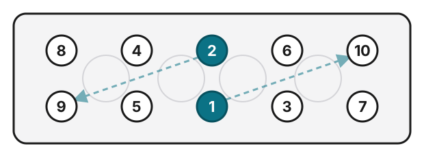
Tightening order (numbers on the nuts): begin at the two centre nuts (1 and 2), then work outward crosswise, alternating diagonally between the rows rather than straight along one row — 3 and 4, then 5 and 6, then 7 and 8, finishing with 9 and 10 at the ends. Top row left to right is 8 · 4 · 2 · 6 · 10, bottom row 9 · 5 · 1 · 3 · 7. Unscrewing follows the same crosswise pattern from the outside inward.
The tightening figures
The head nuts are tightened with a torque-angle method: a low seating torque, then two measured angle turns. The factory specifies this with the 12 mm high nut and a new washer. From the head-data page:
- 8-valve M44.01–.10 (from Model 82): 20 N·m15 ft·lb, then a 90° turn, then a further 90° turn.
- 2.7-litre M44.11/12 (from 1989): 20 N·m15 ft·lb, then a 60° turn, then a further 60° turn.
The angle turns replace any further torque figure — there is no second torque value. The studs stay in the block and are reusable; treat the nuts and washers as single-use, and use a new gasket.
Seating the gasket. The install page also lists a preliminary head-gasket preloading sequence — 20 N·m15 ft·lb, then 50 N·m37 ft·lb, then 90 N·m66 ft·lb — to seat the gasket. This is a preloading step, not the final fastening figure: the head nuts are brought to the torque-angle spec above. Follow the complete workshop-manual procedure for how the gasket preload and the final tightening relate.
Lubrication and washer rules
These rules come straight from the manual and decide whether the clamp load is right:
- Oil the stud threads only. A light film of engine oil on the stud threads — nothing else.
- Never lubricate the nuts or washers. No oil or grease under the nut face or on the washer.
- The washers must not turn while you tighten. If you cannot tell, mark each washer with a paint stripe and watch that the stripe stays put. A washer that spins gives a false torque reading.
- New washers; reuse only if roughened. The manual allows a washer to be reused only after its head-bearing face is roughened with coarse sandpaper — new washers are preferred.
- Fit a new head gasket every time.